ugBASIC User Manual

Blitting operations

The blitting is a data operation used in computer graphics in which several bitmaps are combined into one using a boolean (or mathematical) function.

The operation involves at least two bitmaps: a "source" (or "foreground") and a "destination" (or "background"), and other fields, called "masks" or something like that. The result may be written to a final bitmap, though often it replaces the "destination" field.


The pixels of each are combined bitwise according to the specified blit operation (BOP) and the result is then written to the destination. The BOP is essentially a boolean formula, that can be written in plain ugBASIC instructions. The most obvious BOP overwrites the destination with the source. Other BOPs may involve AND, OR, XOR, and other more complex operations.

A bit of history

The Commodore Amiga and its coprocessor (called "blitter" because of its primary operation) did something analogous to what we are explaining. With only one difference: it was not possible to express any combination but only one of the 256 possible combinations based on the combinatorial calculus called "minterm" in jargon (actually there were many less). Also, the four channels (A, B, C and D) were "fixed" and had given semantics, which could not be changed.In practice: it was difficult to do something complicated (example: thresholds), while it was quick to do something simple (example: masking). Another advantage of Commodore Amiga was that it reasoned in "bitplanes", which made the blit "sequentiable" - something that "packed" (or "chunked") modes would not do. Blitting operations, after the Commodore Amiga, became very common in 90's PC video cards.

For this very same reason, after the theory, we will have to deepen the meaning of the operations in the presence of non-trivial organizations of the bits per pixel, like VIC2, ZX ULA and so on. The granularity of the pixel and any defects in the result due to the limitations of the various video chips must be taken into account.

Usage of blitting

Blitting is similar to hardware-sprite drawing, in that both systems reproduce a pattern, typically a square area, at different locations on the screen. Hardware sprites have the advantage of being stored in separate memory, and therefore don't disturb the main display memory. This allows them to be moved about the display, covering the "background", with no effect on it.


Blitting moves the same types of patterns about the screen, but does so by writing into the same memory as the rest of the display. This means that every time a foreground pattern is placed on the screen, any background pixels underneath it are overwritten, or "damaged". It is up to the software to repair this damage by blitting twice, once to restore the pixels that were changed, and then again to place the foreground pattern in its new location.

There are several ways to optimize this. If large areas of the screen are taken over by the patterns, it may be more efficient to blit the background to the screen instead of erasing each pattern individually. A variation involves dividing the screen into segments and erasing only the segments where patterns have been drawn on. This technique is known as "dirty rectangles".

For those curious: the current implementation is very fast because the blitting expression is converted directly into assembly code, and not interpreted. To explain better, the "put image" BLIT for MOS 6502 is converted in just 6 assembly instructions.

The ugBASIC supplies you with a set of powerful BLIT IMAGE(s), GET IMAGE and PUT IMAGE commands which allow you to grab part of an image into memory and paste it anywhere on the screen. These instructions are mainly used for holding temporary data, since the images cannot be saved along with your BASIC programs. However, the PUT IMAGE and BLIT IMAGE(S) commands can also use images loaded from the computer, with the IMAGE LOAD, IMAGES LOAD and SEQUENCE LOAD commands.

Preliminary example

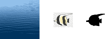
A classic use for blitting is to render transparent sprites onto a background. In this example a background image, a sprite, and a 1-bit mask are used. As the mask is 1-bit, there is no possibility for partial transparency via alpha blending.


A loop that examines each bit in the mask and copies the pixel from the sprite only if the mask is set will be much slower than hardware that can apply exactly the same operation to every pixel. Instead a masked blit can be implemented with two regular BLIT operations using the AND and OR blit operations.

BITMAP ENABLE(16)
CLS BLACK

First, let's set the graphics mode to at least 16 colors, clear the screen, and load the various graphics resources.

mask := LOAD IMAGE("examples/blit_mask.png") EXACT TRANSPARENCY BLACK OPACITY WHITE
background := LOAD IMAGE("examples/blit_background.png")
sprite := LOAD IMAGE("examples/blit_sprite.png")

When preparing the sprite, the colors are very important. The mask pixels are 0 (black) wherever the corresponding sprite pixel is to be displayed, and other color wherever the background needs to be preserved. On the other side, the sprite must be 0 (black) anywhere where it is supposed to be transparent, but note that black can be used in the non-transparent regions.

Since ugBASIC reasons in terms of the native representation, we must use the built-in THRESHOLD operator. Alternatively, we can use the TRANSPARENCY and OPACITY keywords on LOAD IMAGE instruction. We will use the latter.

POSITIVE CONST x = ( SCREEN WIDTH - IMAGE WIDTH(background) ) \ #2
POSITIVE CONST y = ( SCREEN HEIGHT - IMAGE HEIGHT(background) ) \ #2
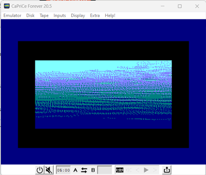
PUT IMAGE background AT x, y

In the first blit, the mask is blitted onto the background using the blit operator AND. Because any value ANDed with 0 equals 0, and any value ANDed with 1 is unchanged, black areas are created where the actual sprites will appear, while leaving the rest of the background alone.

BLIT bop1 AS ( ( SOURCE ) AND ( DESTINATION ) )
BLIT IMAGE mask AT x+10,y+10 WITH bop1

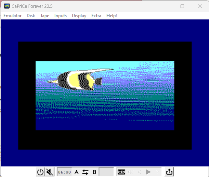
In the second blit, the sprite is blitted onto the newly altered background using the blit operator of OR. Because any value ORed with 0 is unchanged, the background is unaffected and the black areas are filled with the actual sprite image. Note that we are using the "positional" syntax for sources.

BLIT bop2 AS ( ( ( INVERSE ( SOURCE 2 ) ) AND ( SOURCE 1 ) ) OR ( DESTINATION ) )
BLIT IMAGES sprite, mask AT x+10,y+10 WITH bop2

It is also possible to achieve the same effect using a sprite with a white background and a white-on-black mask. In this case, the mask would be ORed first, and the sprite ANDed next. Finally, the very same effect could be obtained by using a transparent PNG and the PUT IMAGE with the WITH TRANSPARENCY.

A bit of theory

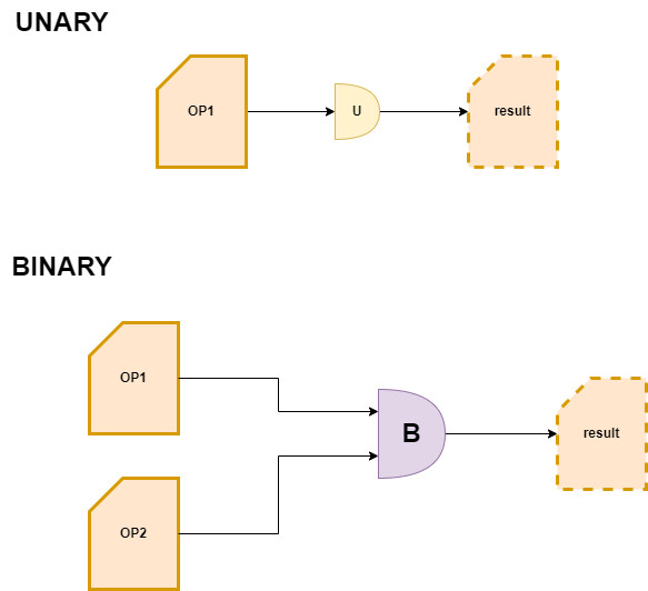
We start to break down the process into a series of elementary steps. In particular, the process has only two operations: unary operations and binary operations.


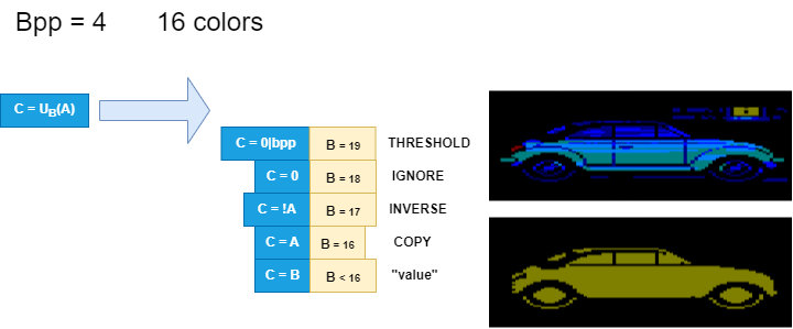
Unary operations take two input parameters: the first (A) is the input value and the second (B) is the type of operation to perform on that input. Output (C) is output, as a result value.

The B value describes the type of operation to be performed: it ranges from copying (COPY, C = A), to complement copying (INVERSE, C = ! A), to assigning a constant value (value , C = value) or, of course, to do nothing (IGNORE, C = undefined). This last case is useful for deactivating the specific step.

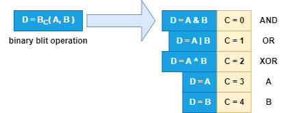
Binary operations accept one more parameter, because they operate on the combination of two inputs: therefore A and B are the input parameters, C the type of operation to be performed while D is the output parameter. It is otherwise similar to the unary operation. We therefore have the possibility of performing a bitwise "and" operation (AND, C = 0), a bitwise "or" (OR, C = 1) or a bitwise exclusive "or" (XOR, C = 2) . Also in this case we have the equivalent of an IGNORE command only that it must be specified whether it is sufficient to copy the A channel or the B channel, as it arrives.

How unary operations works

As anticipated, there are two types of operations that will apply to a blit. In this post we explore operations that deal with a single input image, the so-called unary operations.


Since we try to represent the operations with the lowest number of bits possible, the first positions will be occupied by the possible values according to the depth of the graphics (bpp = bit per pixel) in order to represent a constant value. Therefore, if the first 4 bits are occupied by possible values, we will have 5 overall bits available to represent the operation: this means having 16 additional values, which will be associated with different operations. A key word has been assigned to each operation. To better represent its meaning, we will do it with examples.


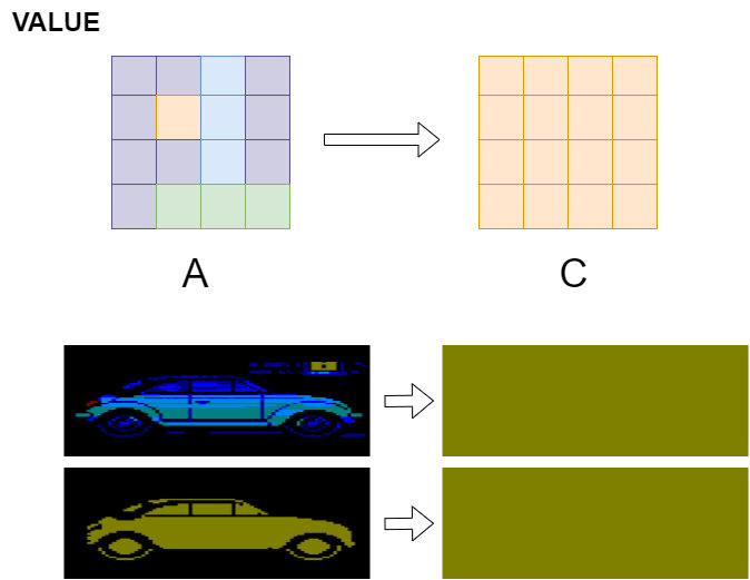
The simplest operation is to assign a specific color value (VALUE x, for example the value 5). In practice, we are filling the surface with the index of a specific color. There are as many values as the color depth of the working graphics resolution. In this case the acceptable values range from 0 to 15.


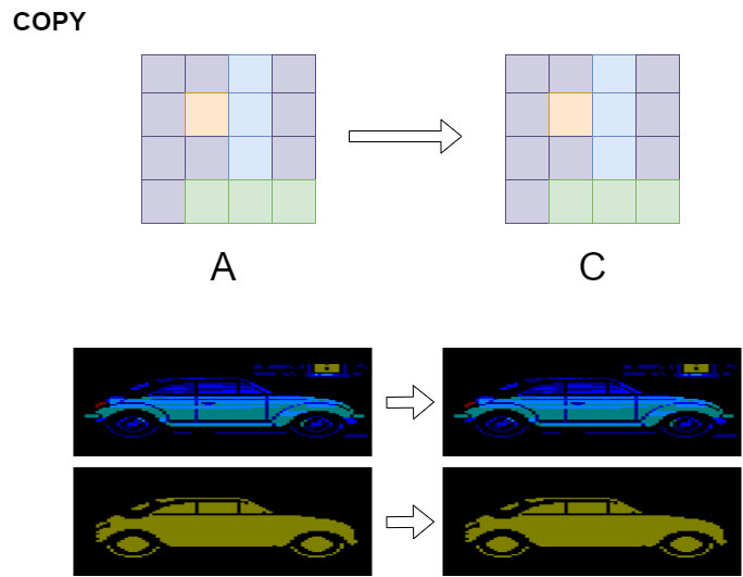
Immediately after we have the possibility to copy the input color (COPY). This possibility allows you to take exactly the input image, and therefore no specific input operations are done.


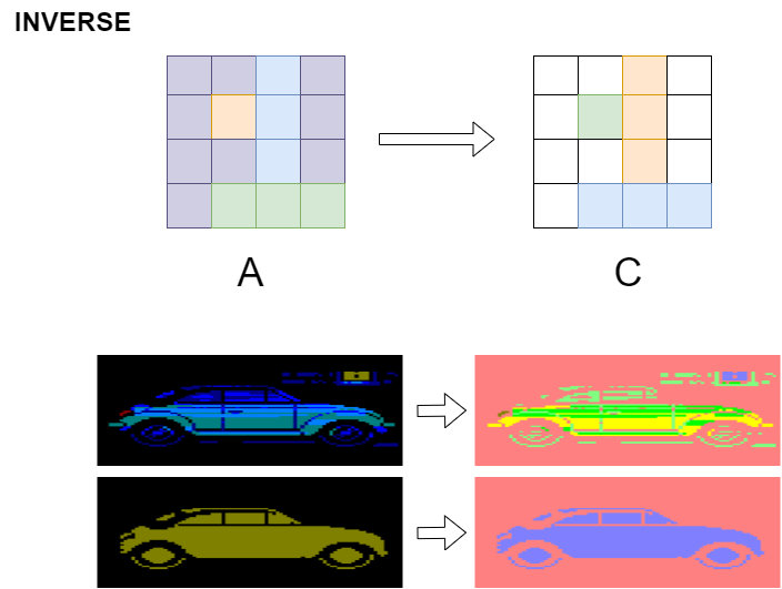
The first operation we can do on the input color is to take its complementary index (INVERSE). In this case, the image that will be obtained will be the same as input but in "negative". Therefore, if the input has a value of 2 and we have 16 maximum colors, the output value will be 13.


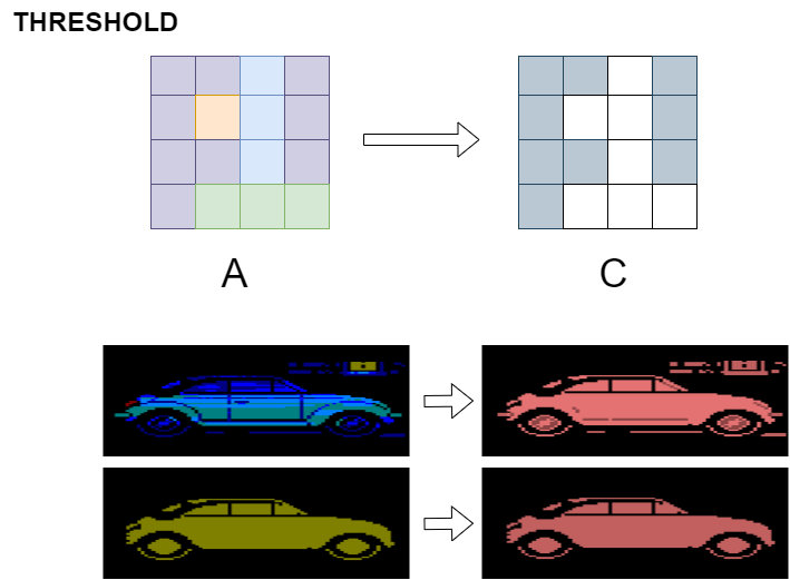
Another interesting operation is to introduce a threshold (THRESHOLD). With this operation, all colors other than zero (0) will assume the maximum available index, in this specific case 15. Note that this is an operation that is performed dynamically, at each execution. If you want to do this when loading the image, then once and for all, you can use the TRANSPARENCY and OPACITY instructions.


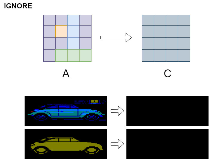
Finally we have the IGNORE operation. This is a special operation, not only because it equals to VALUE 0 but also because it indicates to the system that this operation can be removed, perhaps for optimization.

How binary operations works


Now we explore operations that deal with two input images, the so-called binary operations. In this case the number of bits is immutable, and equals 4 bits. This means that there is the possibility of indicating 16 different operations. A mnemonic keyword has therefore been assigned to each operation and, to better represent its meaning, a hypothetical execution will be shown with examples.
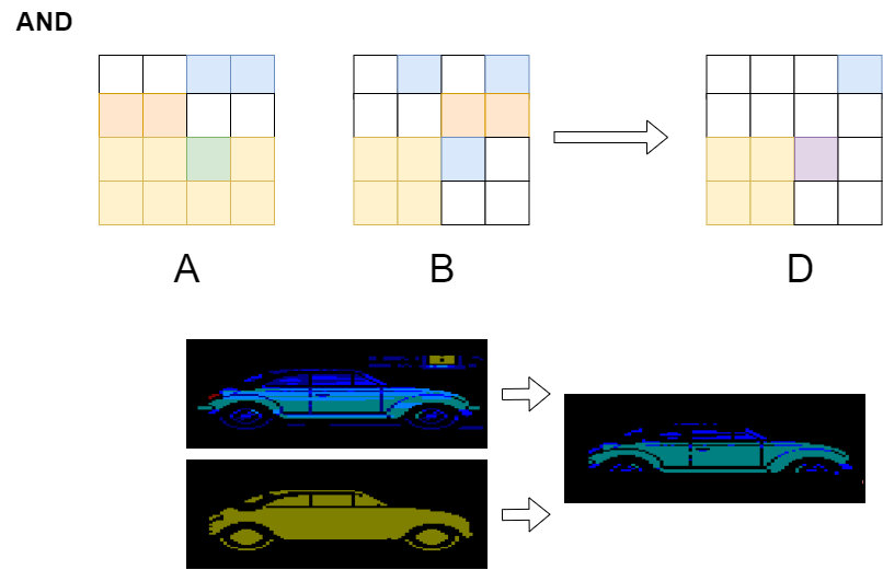

The most common operation is the AND (bitwise "and"). In this type of operation, each color bit is set to 1 only if the corresponding color bit is equal to 1 in both images. Otherwise, the value will be zero (0).
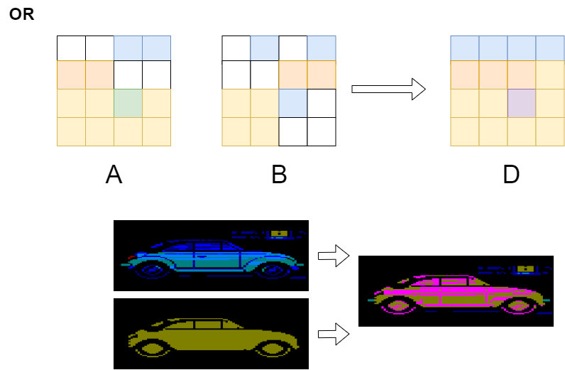

This is followed by the OR (bitwise "or") operation. In this type of operation, each color bit is set to 1 only if the corresponding color bit is equal to 1 in at least one of the two images. Otherwise, the value will be zero (0).
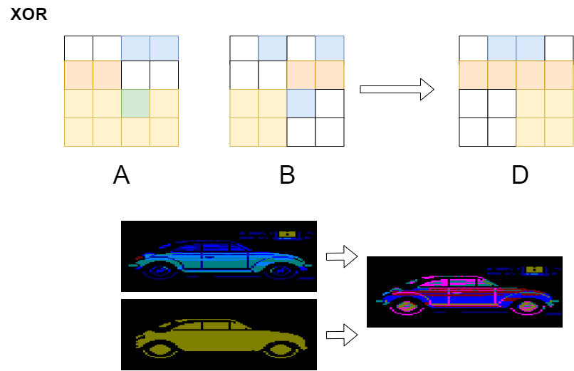

Finally, there is the bitwise XOR (exclusive "or") operation. In this type of operation, each color bit is set to 1 only if the corresponding color bit is different in both images. Otherwise, the value will be zero (0).
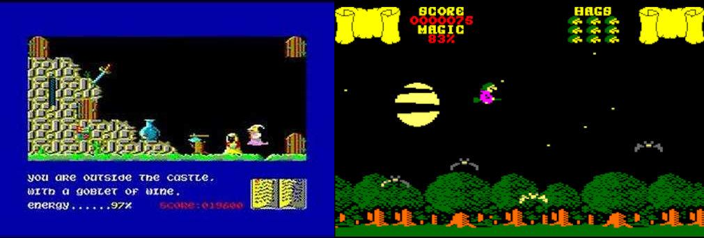

Note that this blit operation has been used on several Amstrad Games like Sorcery, Cauldron and many others. It's an easy way to manage sprites, because it's the same routine to display your sprite and to remove it. That's very easy but the drawback is that your sprite is changed by the background. The only way to prevent it is to use a specific bit pattern in order to avoid color clash after applying the XOR operator. There is a way to customize the blitting operator that could help in this sense.

In addition to these three operations, there are two "non-operations": operation COPY A which copies the color from the first input parameter, ignoring the second, while operation COPY B copies the color from the second input parameter, ignoring the first.
How to use it

After introducing the basic operations, let's start introducing the ugBASIC syntax that can exploit them. We assume that operations, both unary and binary, have parameters. The parameters are obviously the "positional" references to the images you want to use. In turn, these parameters are the actual images, passed as parameters. To this purpose, the convention of indicating each image with the term SOURCE N where N is precisely the image number will be introduced. The image present on the screen (which can also be described as DESTINATION) is conventionally associated with the value N = 0.

Let's start by introducing the syntax to define a blitting operation:

BLIT name AS (bop expression)

The name must be a global and unique identifier which will define the blitting operation. The bop expression must instead describe the operations to be performed between the various images (SOURCE, SOURCE 2, DESTINATION, and so on).

To draw, the BLIT IMAGE(s) command will be used. The syntax of this command will be identical to that of PUT IMAGE (therefore with management of images and sequences), with two main differences. The first is the ability to indicate multiple images (separated from each other by a comma) and the second is to be able to indicate which blitting operation you want to use.

BLIT IMAGE image AT 0,0 WITH name
BLIT IMAGE image1, image2 AT 42,42 WITH name2

The simplest expression is an emulation of the classic PUT IMAGE command:

BLIT putimage AS ( SOURCE )

Assuming that the image to draw has color 0 as background, we can use this expression to draw it in transparency:

BLIT puttrans AS ( SOURCE OR DESTINATION )

Limits

This technique doesn't work, at least not directly, when used in non-trivial graphics systems. Infact, bitwise operations on color displays do not usually produce results that resemble the physical combination of lights or inks. Some combinations are still used to draw interactive highlight rectangles or region borders. When this is done to color images, the unusual resulting colors are easily seen.

One of them is the VIC-II video chip. In this chipset, pixel representation is driven partly by the bitmask and partly by the colormap, where each 8x8 pixel cell is driven by a different set of colors. This makes blitting operations not simple.

Staying on the MOS 6502, I'll now move on to the GTIA (ATARI's video chipset), where instead there are fixed registers for each combination of bits.

We have arrived at the Motorola 6847 chipset, standard for the TRS-80 Color Computer, Dragon 32 and Dragon 64 computers. It is a graphics processor with some specific characteristics, the most important of which is the fact that it encodes a different color for each combination of two bits. In multicolor mode, the combinations correspond to the following colors: 00 = green, 01 = yellow, 10 = blue and 11 = red. In this case the blitting operations modify the color conspicuously. For example, 01 (yellow) AND 11 (red) equals 01 (yellow). Or, 01 (yellow) OR 10 (blue) equals 11 (red). The final effect, when applied to images, is not very realistic: in particular, the masking is unrecognizable. The fenomena going on is similar to the use of OPTIONS on commands GET/PUT with boleans.

The first implementation for TMS 9918, the "standard" video chipset with MSX machines and the various consoles, is a bit disappointing: in practice, you don't see the masking, neither with the OR operation nor with the THRESHOLD one. While I was looking in the code for the reason for this behavior, and the doubt of having introduced bugs doesn't go away immediately, I realized a conceptual error that I introduced.

I state that this reasoning is valid for chipsets that have a color map, therefore it is valid for TMS 9918, MOS VIC-I, MOS VIC-II, MOS TED and not for THOMSON EF936X, MOTOROLA 6847 and Amstrad CPC video chipset.

The premise is simple: some time ago a very efficient algorithm was introduced for the representation of images with many colors, when the target resolution allows precisely to define different colors for each "tile" or cell. This algorithm tries to optimize the use of colors, and it is not uncommon that the combination 0 (or 00 for chipsets with 2 bits / color) is assigned a color other than black or in any case from the background color. Maybe, since it's a solid white square, it's rendered with a combination of all zeros and the dominant color.

Too bad that, when blitting is done, the value 0 is equivalent to transparency. Which means, in other words, that although something has been drawn, in practice it is an "empty" image, from the point of view of the bitmap.

The solution? Prefer the value 1 for values other than the black value, and favor the value 0 for values similar to the black value. Obviously, we are talking about parameters that can be indicated.

Finally, the implementation for EF936x, the chipset found in the Thomson MO5, MO6 and Olivetti Prodest PC128 computers, is complete. On this chipset there is the possibility of programming up to 16 registers with RGB components, and this flexibility goes very well with the management of the color indices.

Any problem?

If you have found a problem, if you think there is a bug or, more simply, you would like something to be improved, write a topic on the official forum, or open an issue on GitHub.

Thank you!